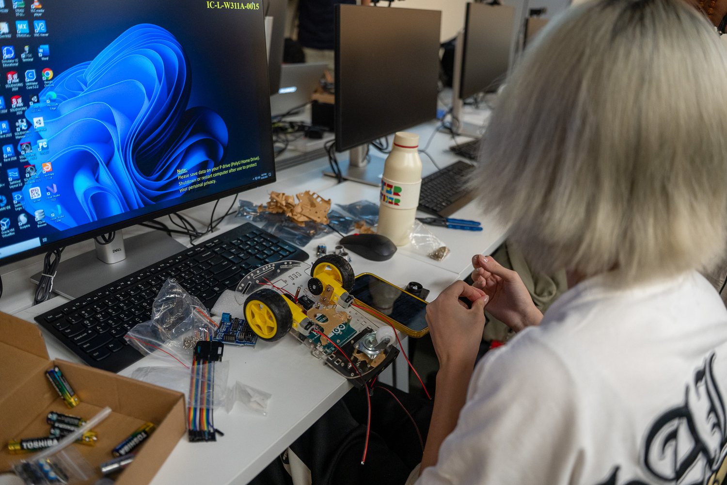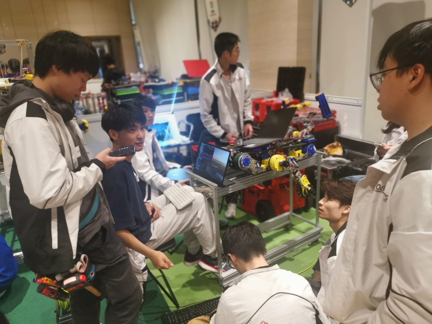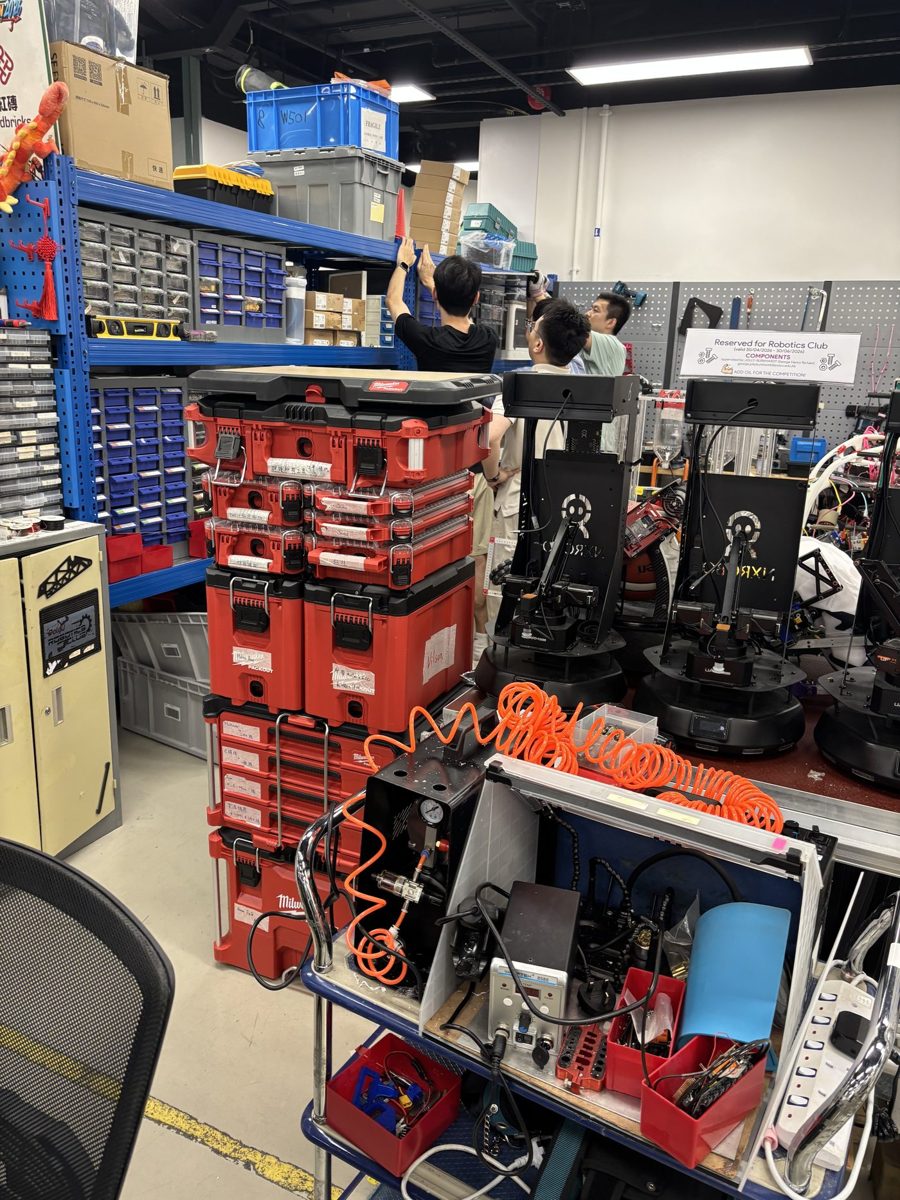
The Electronics & Embedded Systems group gives the robot power and connects every part of it. Members design the battery and power system, build circuit boards and wiring, drive the motors and write the firmware on the microcontrollers that read sensors and send commands.
Most robot failures at competitions are electrical: a loose connector, a brown-out or a noisy signal. This group designs for reliability and safety, with fuses, emergency stops, clear wiring standards and tests before every run.
- Mentor
- Yang Mokui
- Student representatives
- To be announced after the 2026 placement
- Tools
- KiCad or Altium, STM32 and ESP32, CAN bus, oscilloscopes, bench power supplies
- Works on
- Robot power systems, motor control for Robocon and the robot dog, sensor interfaces for drones and vehicles
What the group works on
Power systems
Battery choice, power distribution, fuses, voltage regulators and the emergency-stop circuit.
PCB design
Schematics, layout and assembly of control, driver and interface boards.
Motor control
Motor drivers, encoders and current and speed loops for wheels, arms and leg joints.
Embedded firmware
Real-time code on STM32 and ESP32 microcontrollers: drivers, timing and fault handling.
Communication
CAN, UART, SPI and I2C between boards, and the link to the onboard computer.
Wiring and testing
Harnesses, connectors, labelling, noise reduction and test procedures before every run.
Engineering foundations
A few of the equations members use in this group. Training sessions build up to them step by step.
Battery runtime
Estimated operating time from battery capacity C, nominal voltage, system efficiency and average power draw.
DC motor model
Torque is proportional to current; the supply voltage covers the resistive drop and the back-EMF at speed ω.
PWM average voltage
A motor driver sets the effective voltage through the duty cycle D of its switching signal.
Conductor loss
Heat in wires and connectors. Used to size cables and choose connectors for high-current motor lines.
Discrete PI current loop
The inner control loop that runs on the microcontroller at a fixed sample time T_s.
RC low-pass filter
Cut-off frequency of a simple filter that removes switching noise from sensor signals.
What we expect from members
Expectations grow with the member tier. Tiers are reviewed regularly, so members can move up as their skills grow.
Curiosity about circuits and microcontrollers. Learns soldering and lab safety in introductory sessions.
Can read schematics, solder reliably, program a microcontroller and use a multimeter and oscilloscope; follows battery safety rules.
Owns the electrical design of a robot, designs power and control boards, sets wiring standards and mentors Tier 2 members.
Before you join: Basic circuit theory, a microcontroller project (Arduino, STM32 or ESP32) and some C programming are good starting points. No member is expected to know everything at the start.
Photos