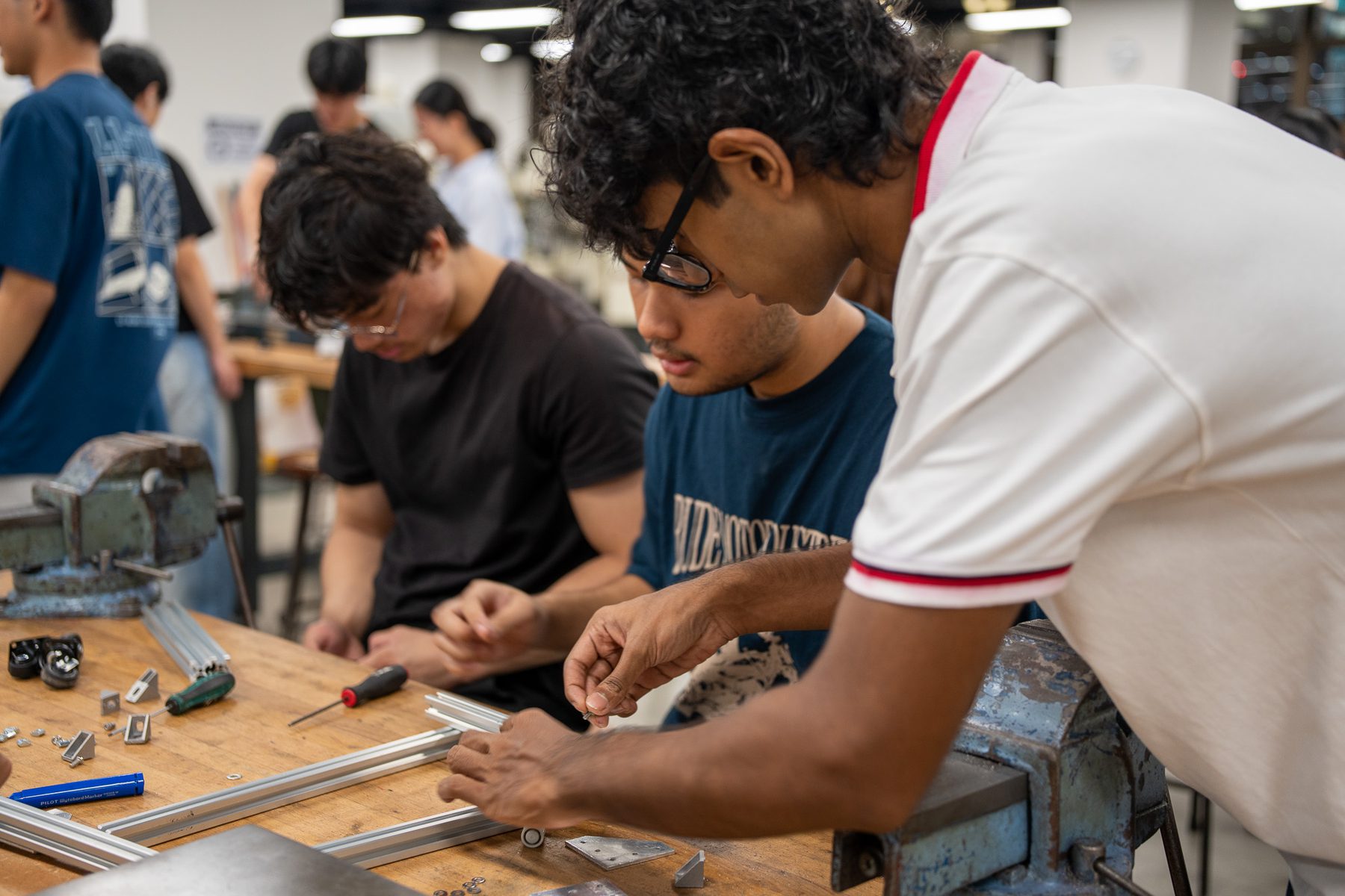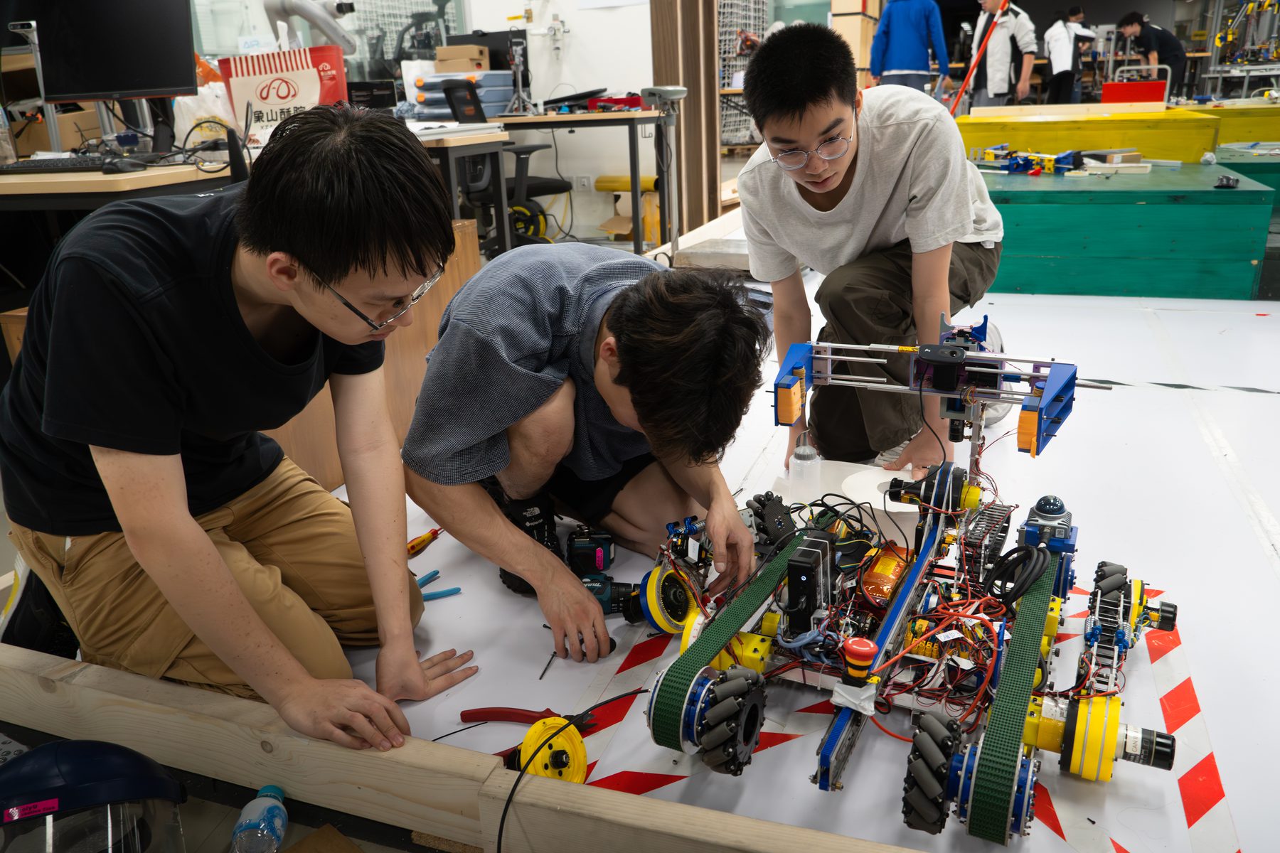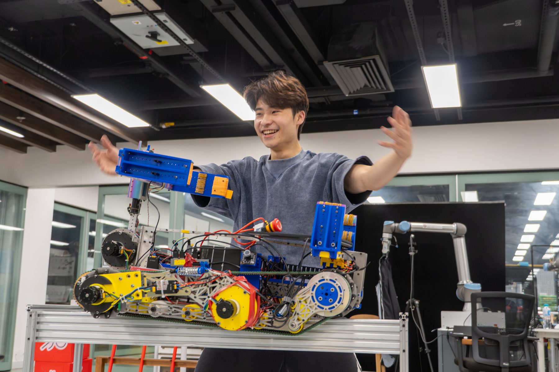
The Mechanical Design group turns an idea into a physical robot. Members decide the robot's shape and size, design the frame, legs, arms, grippers and drive trains, choose materials, motors and gearboxes, and then make and assemble the parts in the PolyU Industrial Centre.
Every other group depends on this work. A mechanism that jams, a frame that flexes or a robot that tips over cannot be fixed in software, so mechanical members check loads, stiffness and stability before anything is made, and design robots that can be repaired quickly at a competition.
- Mentor
- Hu Jiahao
- Student representatives
- To be announced after the 2026 placement
- Tools
- SolidWorks or Fusion 360, basic FEA, 3D printers, laser cutters, CNC machines
- Works on
- Robocon 2027 mechanisms, the robot dog legs and frame, drone frames and payload mounts
What the group works on
CAD and drawings
Part and assembly models, engineering drawings and design reviews before any part is made.
Mechanisms
Linkages, gearboxes, lifts, grippers and suction tools for handling game objects and payloads.
Drive trains and legs
Omni, mecanum and swerve drives for ground robots; leg joints and linkages for quadrupeds.
Structural checks
Hand calculations and simple FEA for loads, stiffness and safety factors; weight budgets.
Fabrication
3D printing, laser cutting and CNC machining, with Industrial Centre engineers supervising.
Integration and repair
Mounting points for electronics and sensors, cable routing, spare parts and fast access for repair.
Engineering foundations
A few of the equations members use in this group. Training sessions build up to them step by step.
Bending stress in a beam
Checks that a chassis rail or arm will not yield under load. M is the bending moment, y the distance from the neutral axis and I the second moment of area.
Safety factor
Yield strength over the largest working stress. Robot parts that take impacts are usually designed with a clear margin above 1.
Motor torque through a gearbox
Torque the motor must give to push force F at radius r through a gear ratio N with efficiency η.
Two-link leg kinematics
Foot position of a robot dog leg from its hip and knee angles: the starting point for leg design and gait control.
Mecanum wheel kinematics
Wheel speeds needed for a chosen sideways, forward and turning motion of an omnidirectional competition robot.
Tipping limit
A robot with its centre of mass at height h and distance d from the edge of its wheelbase tips over above this acceleration. Lifting mechanisms raise h.
What we expect from members
Expectations grow with the member tier. Tiers are reviewed regularly, so members can move up as their skills grow.
Interest in how machines work. Learns basic CAD and workshop safety in introductory sessions.
Can model parts and assemblies in CAD and produce drawings; has completed Industrial Centre safety training for the machines used; takes part in design reviews.
Leads the mechanical design of a subsystem or a whole robot, does load and stability checks, runs design reviews and mentors Tier 2 members.
Before you join: Statics and mechanics of materials, a CAD tutorial (SolidWorks or Fusion 360) and any hands-on building experience are good starting points. No member is expected to know everything at the start.
Photos